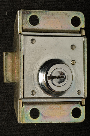
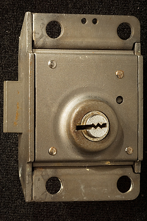
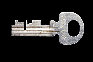
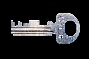
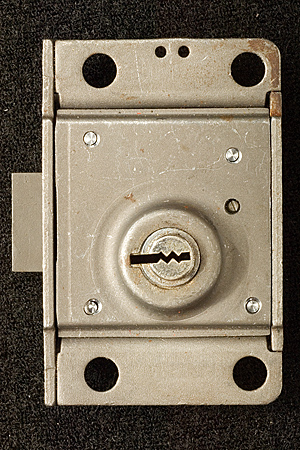
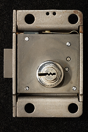
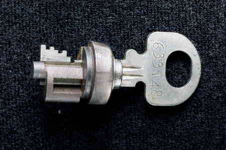
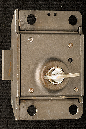
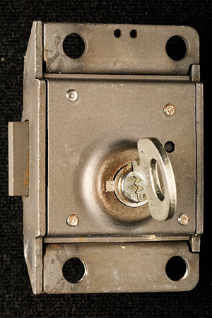
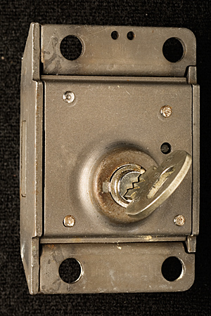
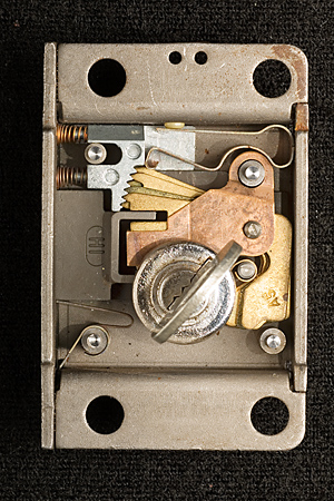
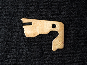
Notes on Western Electric (Bell System) Coin Telephone LocksMatt Blaze16 June 2005 (minor revisions 24 June 2005)Among the most interesting, and formidable, lever-tumbler locks in the United States were made by the Western Electric company to secure (former) Bell System coin telephones. (Similar locks were also made by Northern Electric and Automatic Electric to serve the Canadian and US independent telco markets.) These locks (as well as the payphones themselves) were required to withstand considerable physical abuse and function reliably for long periods with only limited maintenance. The design is thought to effectively resist virtually any practical picking or bypass attack to which it might be realistically exposed in the field. Tens of thousands of the various original versions of these locks remain in service across the country today, over 20 years after the breakup of the Bell System. The standard Western Electric / Bell System single-slot ("fortress") payphone was equipped with two locks, as are current models from other vendors. One protects the "upper housing," which contains the phone's electronic components, while the other protects the "coin vault," which contains the collected revenue. (This arrangement allows service technicians to be given maintenance access but not cash access.) Typically, upper housings in a given area might share a common key, while coin vaults would be uniquely keyed and coin collectors issued large rings of keys for all the phones on their rounds. A standard lock module, roughly 2 inches by 3 inches by .67 inches (plus a small lock bolt that protrudes out about .35 inches), fits both the upper and lower housings. (The lock bolt does not directly secure the housing or coin vault, but rather functions much like the bolt of a modern safe lock package, blocking or releasing other boltwork built in to the phone chassis itself). Several different models have been produced over the last 50 years, in a variety of finishes and with various security features. A single keyway profile (with a distinctive "zig-zag" design) is shared by many of these locks, although keys for different models are cut differently to accommodate specific lock features (the non-Western Electric locks use a slightly different keyway profile). Locks have been produced with as few as five and as many as eight levers, with six different cut depths used for each lever. By the end of the Bell System era (after which time payphones became less homogeneous), most telephone companies used the "29B" lock (with five levers and a keyspace of 7,776 unique changes) on the upper housing and the "30C" lock (with eight levers and a keyspace of 1,679,616 unique changes) on the coin vault. Figures 1 and 3 show a 29B lock and its key; Figures 2 and 4 show a 30C lock and its key. Note that the codes stamped on the keys are indirect.
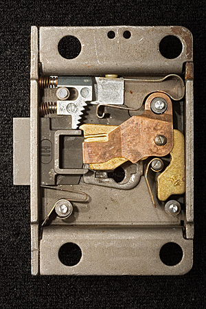
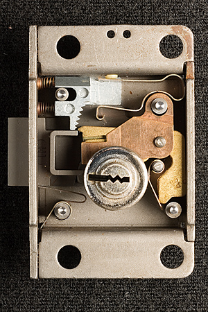
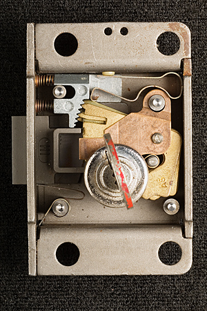
DisassemblyAlthough still in use by many former Bell System and independent telephone companies, working 29B and 30C locks are readily available on the used and surplus markets, typically costing $5 to $15 each in small quantities. While these locks were not intended to be field serviceable, it is not difficult to (slightly destructively) disassemble a lock package to observe its components and operation. The lock package is held together with four rivets, with heads that can be removed easily under a small drill press or milling machine. See Figure 5. Once the rivet heads have been removed, the outer faceplate is easily pried off, revealing the plug/curtain assembly and the inner plate. The inner plate is occasionally made of hardened material and provides some protection against drilling attacks. See Figure 6.
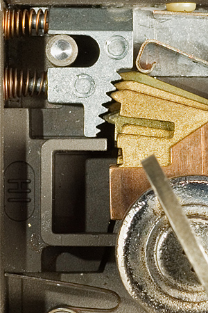
At this point, the plug and inner plate can be removed to expose the levers and other internal mechanisms (Figure 7). The plug itself (Figure 8) defines the keyway profile and also acts as partial curtain (although it does not entirely prevent access to the lever bellies with the plug in a neutral position, so it does not really meet the usual definition of a curtain). Plug rotation transmits to the bolt with or without a key in the lock.
OperationThe basic principles of operation are substantially similar to those of other lever locks, although there are several unusual features. In the neutral (zero degree), locked position the levers are held in their lowest position by a common leaf spring that presses against the plug (to the right of the keyway at the base of the levers). (The spring above the lever pack presses against the levers as the plug rotates). See Figures 9 and 10. As the plug rotates (with or without a key), the fence (attached directly to the lock bolt) is drawn toward the lever pack. At about 70 degrees of clockwise rotation, the key is in full contact with the lever bellies and the lever pack reaches its keyed position. By 80 degrees. the bolt begins to retract and the fence makes contact with the lever gates. This is the maximum rotation possible with an incorrectly keyed (or unkeyed) lock. See Figures 11 and 12. If the correct key is inserted, the plug can rotate beyond 80 degrees; at about 100 degrees, the fence is fully through the gates and the bolt is fully retracted. (The key can rotate up to a maximum of about 120 degrees). Observe that the design is key retaining; the key cannot be removed except in the neutral, locked, position. See Figures 13 and 14.
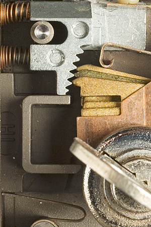
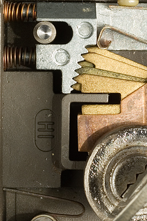
Unusual featuresThese locks incorporate several unusual features that contribute to their security and reliability. First, observe that, unlike most lever locks, there are two common springs shared by all levers (rather than individual springs associated with each tumbler). This reduces the feedback available to the lock picker, since it is difficult to use the spring pressure to determine the position of any individual lever or to reset individual levers as they are being manipulated. (A similar shared-spring design is used for the sliding tumblers in Bramah locks.) The common spring also serves simplicity and ruggedness. The shared leaf springs are considerably larger and more robust than smaller per-lever springs would be, leaving fewer small components to fail or jam. The patent on this arrangement was filed in 1966 (US patent number 3,402,581). (The patent also mentions other features that do not appear to be incorporated into recent versions of the locks, including levers with different centers of rotation and an electrical contact that triggers an alarm when any lever is raised). 29B (but not 30C) locks include fixed vertical wards in place of two of the lever positions. One of these wards requires a deep cut in the key in order for it to be able to turn (easily identified in the 29B key in Figure 3, above). The most unusual feature of these locks, however, is the serrated spring-loaded "tumbler lock" visible in the upper left corner of the cutaways above. (This feature is included in most 30C locks but does not appear to be present in 29B locks.) Although resembling a ratchet, that is not its function (and, indeed, it is not actually a ratchet, since it does not permit further movement in any direction once engaged). Instead, the tumbler lock effectively fixes the levers in place once they have reached their keyed heights but before the fence makes contact with the gates. When the bolt is fully retracted and as the key bitting raises the levers, the spring-loaded serrated tumbler lock is pulled back from the levers and does not interfere with their movement. See Figures 15 and 16.
Once the levers reach their keyed height and the bolt begins to retract (but before the fence actually makes contact with the gates), the tumbler lock releases and fixes the levers into position, with very little upward or downward play possible. Observe that this makes it effectively impossible to pick or impression the lock using conventional techniques that depend on friction from the fence against the gates. The "binding" of each lever tumbler is always the same, whether its gate is at the correct height or not. A second benefit of this mechanism appears to be reliability: the tumbler lock "corrects" each lever to its nearest discrete bitting height, and so locks continue to operate smoothly even as the keys or levers wear. See Figures 17 and 18.
DiscussionThis is a remarkable lock. The basic design has been used for at least 50 years, with the sophisticated security features in the latest models dating back almost 40 years. Often deployed in hostile environments and an attractive target for vandalism and theft, these locks have enjoyed an exceptional track record over their history. Although there were persistent rumors in the late 1970's (approaching urban legend proportions) of an individual who supposedly could (and did) pick these locks, successful surreptitious attacks have never been credibly substantiated in spite of the obvious financial incentive for criminals as well as telephone companies to discover them. (Most documented theft from coin boxes involves either employees with access to keys or outright destruction and/or removal of entire telephones). Similarly, there was apparently no lock bypass procedure documented among the standard Bell System Practices. In the rare cases where a key was lost or a lock malfunctioned, the entire phone would be forcefully removed (by any ad hoc method that could be made to work) and returned to a repair facility for destructive opening. While the design resists conventional picking and impressioning, it appears to be potentially vulnerable to other kinds of decoding attacks, although they would require special tools and techniques to carry out. It may be possible to systematically record the precise amount of plug rotation with different key bittings to identify the true gate locations, much as Group 2 combination safe locks can be "manipulated" to discover the positions of individual wheel gates. This approach is probably not practical in the field, however, since the key rotates over a limited range and decoding would therefore require very precise measurements (as well as either a special "variable key" or the ability to cut test keys as the attack is being carried out). It may also be possible to pass thin tools through the keyway to contact the gate surfaces of the levers, and so it might be possible to identify the gates and measure their positions to decode the lock that way. Again, I am aware of no such tools ever having been documented or even proposed, and a successful non-destructive attack against this lock would constitute quite an accomplishment. The lock also resists destructive attack reasonably well, especially in its installed environment. The telephone housing provides drill resistance for everything except the plug, which is of course exposed. However, drilling the plug itself would appear to offer little benefit to the attacker; the integrity of the locking mechanism does not depend on the presence of the plug. The obvious drilling attacks involve either removing the fence from the bolt or destroying enough of the levers to allow the bolt to move unimpeded. However, straight access to these parts requires compromising the hardened chassis of the telephone itself. Furthermore, because the locks are mounted on the side of the telephone, performing such attacks in the field would be cumbersome at best, especially given the restricted spaces in which payphones are typically installed. The proven success of this lock mechanism is even more impressive when considering its other requirements. Payphone locks must resist not only larceny but also vandalism and sabotage that does not necessarily aim to open the lock but that intends simply to deny access ("There are quite a few people who actually dislike The Phone Company"). The mechanism is particularly robust against jamming or insertion of foreign objects or adhesives, and is designed to be relatively easy to clean from outside the housing through the keyway. The overall design is relatively simple and requires few high-precision components, allowing it to be mass produced inexpensively while still maintaining high security.
|